Erased cell hasn’t charge (electrons) stored in gate and threshold voltage of transistor is Vt1. Charge is transfered into the gate during programming and increases threshold voltage to Vt0. During read operation Vref voltage is connected to gate and current between drain and source of transistor is evaluated. Cell is programmed if current is lower than predefined threshold. This status corresponds to logic level 0 (L). Oposit case is evaluated as logic level 1 (H). Erase operation removes charge from gate and threshold voltage returns in ideal case to value Vt1.


In the practice during programming isn’t stored always the same charge into gate, after erase operation some charge can remains stored in gate also read operation can disturb charge stored in adjacent cels. Threshold voltages difference decreases after each programming/erasing (P/E) cycle until finally reach value when it is not possible to distinguish between programmed and erased state. Because of this, every flash cell has limited number of P/E cycles. As dimmensions of cell decreases number of P/E cycles also decreases.
SLC (single-level cell) flash
SLC flash cell stores 1 bit. Cell is erased if Vt belongs to area 1, if it is located inside area 0 then cell is programmed.

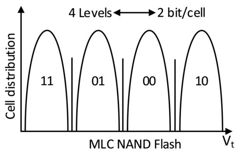
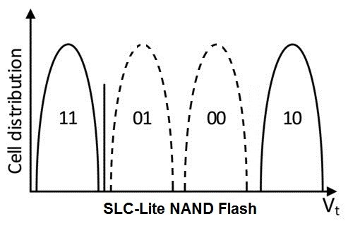
SLC-Lite technology is based on MLC flash but firmware is changed in a such way that it only uses states 11 and 10 (maximal threshold voltage difference)
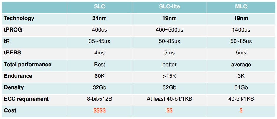
SLC, SLC-lite and MLC flash comparison (based on Toshiba flash chips)
The first samples of Apacer memory cards with capacity 4GB and 8GB we have in our stock. In case of interest please contact us at sales@soselectronic.com.
- Number of P/E cycles increased 5 times
- Programming is 4 time faster than for MLC
- Read performance almost the same as for SLC
- Cost is 40 to 50% lower than SLC flash
- Only half capacity of MLC flash
Do you like our articles? Do not miss any of them! You do not have to worry about anything, we will arrange delivery to you.





![What Do Apacer SSDs with PCI Express 4.0 [X4] Interface Bring? What Do Apacer SSDs with PCI Express 4.0 [X4] Interface Bring?](http://cdn.soselectronic.com/novinky/obr/obr2904_uput_m.jpg)

