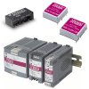
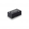
See, for example, the title page of TEN 8-2411WI. DC/DC converter datasheet. You can see 8W and operating temperature range –40 to 85°C. If you stop reading here, you will believe that the converter is able to deliver 8W at 85°C ambient temperature.
If you read further, you will see that for the ambient temperature higher than 70°C, you have to decrease converter load by 3%/Kelvin. Maximum allowed load at 85°C will be 100-(85-70)*3=55% of full load=4,4W.
When you start with thermal testing, an obvious question arises – at which point should I measure the ambient temperature? Unfortunately, datasheet or application note doesn’t help you. In addition, there is also a lot of confusion about where to measure ambient temperature. Please, see the article What is ambient temperature, anyway, and why does it matter?
TRACO is aware of this situation and is therefore updating datasheets to make all things clear. Until they complete their work, we will share the information from TRACO technical support with you.
Ambient Temperature
To measure an ambient temperature around a DC/DC converter, it is recommended do the measurement at a distance of about 2 cm from the component under worst-case conditions until the temperature stops rising. It is important to measure temperature inside the final product because other components producing heat, enclosure, cabling, connectors or other mechanical parts inside enclosure affect the temperature around DC/DC converter.The maximal converter case temperature should also not be exceeded. The application note defines the exact point where it is necessary to measure the case temperature. If the exact place is not defined, measure at the centre of the top of the inverter.
The greater the difference between the measured temperatures and the maximum allowable temperatures, the longer the lifetime of the DC/DC converter will be assumed.
Why Derate Output?
Every component used in DC/DC converter has its own lifetime, reliability and thermal limit. For semiconductor devices (FETs, ICs, etc.), mostsuppliers specify maximum junction temperature T_j,max = 150°C. It is impossible to measure T_j directly, therefore manufacturers developed procedure, which estimates T_j from temperature of the case and the leads.For opto-couplers, manufacturers usually specify maximum case temperature T_case=100-110°C. Magnetic cores temperature is often limited to T_body=125°C. PCB surface temperatures are limited typically to T_surface=120-130°C.
To make DC/DC converter long-term reliable, manufacturers keep some margin and don’t push components to their limits. Typical temperatures are T_j=125°C, T_case=100°C, T_body=120°C, T_surface=120°C. For more information, please see the article Thermal Characterization Process for Open-Frame Board-Mounted Power Modules as an example.
TRACO datasheets typically mention linear derating coefficient, for example, 3%/Kelvin. Application note also provides derating curves versus air velocity. It is natural that more airflow provides more efficient cooling. Air velocity is usually in LFM (Linear Feet per Minute) units. By multiplying air velocity by the cross section of area where air is flowing, we can determine the air volume flowing through this area per unit of time. Volume flow is usually measured in Cubic Feet per Minute (CFM).
Do you like our articles? Do not miss any of them! You do not have to worry about anything, we will arrange delivery to you.


