The fact is, data collected in the laboratory differs from data collected from actual usage. How does that happen? Ultimately it should be clear to everyone that a car tested with no weight inside on a defined test track consumes less than when it’s fully loaded with a family of four on the side of the nearest mountain.
To make a final decision while picking the suitable car, you consider several circumstances. Why? For example Porsche 911 is a fabulous car but you would not use it for an expedition through the South Africa – where a 4-wheel drive Jeep would be the better option.
Selecting the appropriate power supply is even more complicated and it is mostly not about budget. How do we go about choosing the right components to deliver power?
Analysing the Requirement
The first step is to define what the respective power supply is required for.
The key objective is to bring input voltage for the application to a new potential.
- Should potential be divided or not?
- How reliable should the whole circuit and application be?
- What is the end product?
- What design do I have space for? Do other components on the board influence this?
- In which environmental conditions will the application be used?
- What is the input and output voltage ranges? What is required at which output current?
- Which regulations (industrial, railway or medical) need to be followed?
We’d probably all like a converter that meets all the necessary requirements in one go – an off-the-shelf solution, but usually, we need to spend more effort – that’s because we need more than one converter to meet requirements or additional wiring to achieve the values we require.
So, what do we need to establish to find a solution?
The first step is to determine which measurement values we need – a simple measurement allows us to easily make a rough assessment: input and output voltage and current on the converter, on the load and possible changes in efficiency.
1. How can I measure correctly and avoid errors?
Every measurement changes the actual state of the circuit and any impact needs to be kept as minimal as possible.
This means that doing a 4-wire measurement even for a "simple measurement“is advisable. Measuring current and voltage with independent test leads means that the leads ‘inherent resistance will have less impact on values. Do not forget about end usage.
For example, in an opera theatre, there can be 30m wires between the power supply and the actual load. If the load required is 24V the source needs a higher output voltage to offset voltage loss in the wire.
That means that both load and source need to be measured. Please see below an example of a classic 4-wire voltage measurement at source.
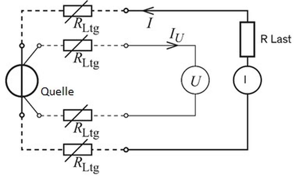
Pict.1: 4-wire voltage measurement at source and load
2. How do I deal with Ripple & Noise?
Regardless of application the ripple and noise of a DC/DC converter could lie in its actual area of operation, for example in a measuring bridge, so as a result, this needs to be considered and evaluated separately.
We talk about Ripple in AC/DC an DC/DC circuit when irregular disturbances are caused by internal circuits, whereas Noise denotes the peaks that return periodically, produced by the transforming pulsing at switching frequency.
To determine actual values the probe head must be in direct contact with:
- the pins,
- the ground ring,
- the measurement tip (See Pict. 2)
In order to be able to compare results with manufacturers data, bandwidth on the oscilloscope is limited to 20MHz, a common value for laboratory work.

Pict. 2: Correct application of measurement tips to a DC/DC Converter with pins
Usually, noise and ripple can simply be reduced with two parallel-switched capacitors. For example, a 100nF metal film capacitor and a 10µF electrolytic capacitor. Always bearing in mind that values presented on datasheets can be influenced by other factors during end usage.
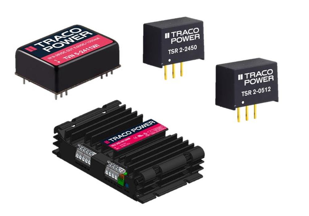
Swiss manufacturer Traco Power’s product portfolio includes more than 25 families of 3 Watt DC/DC Converter ranges, such as the TVN Series with ultra-low Ripple & Noise or the THM series, which is certified for medical applications, open-frame variants or the TMR-WIR series approved for railway applications with 3000VDC isolation voltage - a whole host of possibilities.
3. What happens in the event of inrush current?
The information is important for ensuring that components upstream are the correct dimensions.
- Current depends essentially on switching speed, so ideally mercury switches should be used in the laboratory
- Source should have lowest internal resistance possible
- Current is measured with a demagnetised tip
Ambient temperature also has a big impact on inrush current. For example, the use of electrolytic capacitors is highly dependent on temperature.
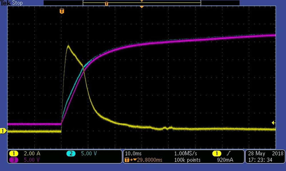
Pict. 3: Inrush voltage of a DC/DC converter in a non-active state (cold = room temperature 25°C)
Diagram shows an example of inrush voltage in a LED lamp (yellow line). The image also shows the voltage pattern in the lamp in purple. It is good to see the point at which the device was switched on marked (T, in orange), which reaches its maximum value at around 10A and within 10m/s has returned to 300mA again.
If you are having issues with inrush voltage affecting a circuit, using a thermistor (NTC) can help.
4. What do I need to be aware of with respect to electromagnetic compatibility? (EMC)
It’s important for the general application. Using a DC/DC converter with an internal filter doesn’t automatically mean that you’ll adhere to the values specified for the application. As you know EMC compatibility can often be affected by several components.
In many cases, the output voltage must be connected with protective earth for safety reasons which can have a significant impact on EMC. However, the power supply manufacturer can offer advice regarding how to adhere to EMC values.
Most power supply manufacturers provide help in the form of suggestions for suitable filters on their websites. For example, at Traco Power these can be downloaded directly from the relevant device’s page.
Before any assessment and selection, it is important to define your requirements clearly, and there is a big difference between deciding on what you really need, and what you would like.
Coming back to the car manufacturers we referred to, it is important to think about how measurements can be taken correctly, and how every measurement impact value gathered. Testing strips and laboratory conditions are defined when a circuit is built, but what are the conditions that circuit will actually be used in?
Meeting EMC requirements depends heavily on the field of application and its prerequisite conditions, just as with ripple and noise and inrush current.
It is well-known that there are many manufacturers out there, so the quality, as well as price of a specific product, can vary greatly.
If you are interested in other Traco Power products, or you need more information, please contact us at sales@soselectronic.com
Source: Florian Haas, Traco Electronic AG,
Do you like our articles? Do not miss any of them! You do not have to worry about anything, we will arrange delivery to you.
