


Diotec Takes the Leap from Diodes to IGBT Technology
Diotec has expanded beyond diodes and now offers MOSFETs, IGBTs, and SiC transistors. Its latest addition, IGBT transistors, comes in TO-247-3 and TO-247-4 packages, supporting switching up to 75 A at 650 V and 40 A at 1 350 V at a chip temperature of 100 °C. During 2025, the company plans to introduce IGBTs rated for 115 A at 650 V and 100 A at 1 200 V.
IGBT Cell Structure
Figure 1 below shows a cross-section of a single IGBT cell, which includes a vertical (trench) gate and a field-stop layer that improves the electric field drop inside the chip. The cell typically has a width of 2 to 10 μm. The silicon IGBT chip incorporates millions of these cells, enabling it to switch currents in the hundreds of amperes. For switching voltages of 650 V, the typical thickness of the IGBT chip is between 65 and 75 μm.
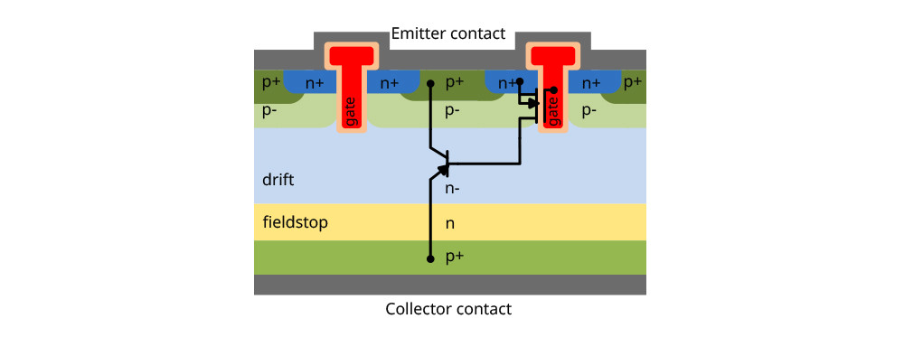
n– represents lightly doped n-type, n stands for standard doping, and n+ indicates heavily doped. The same applies to p-type semiconductors.
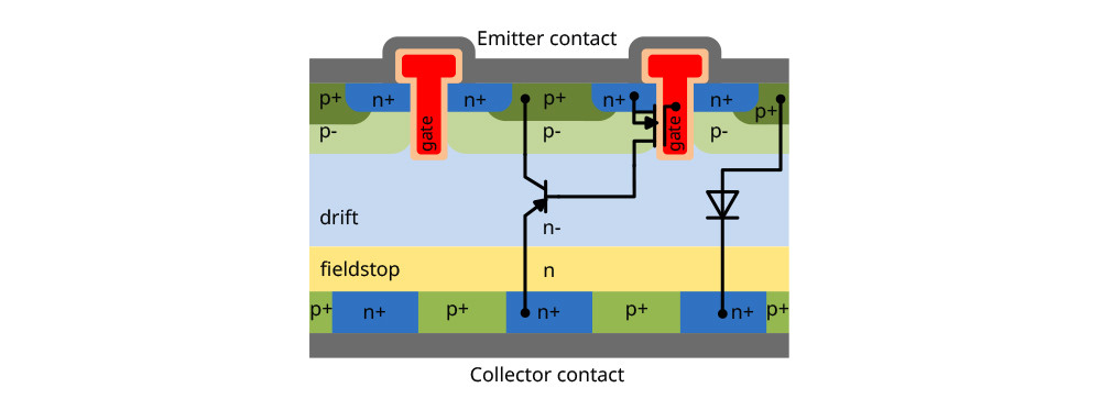
The IGBT in Figure 1 easily accommodates the addition of an antiparallel diode. The lower p+ region is split into alternating p+ and n+ areas connected to the collector, creating a diode with the structure p+, p–, n–, n, n+.
IGBT Equivalent Circuit
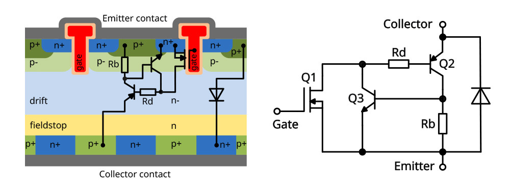
Rd represents the resistance of the n– drift region, while Rb is the total resistance of the p– and p+ regions.
The operation is simple: a positive voltage between the gate (G) and emitter (E) turns on MOSFET Q1, activating the PNP transistor Q2. The IGBT also includes a parasitic NPN transistor Q3.
In theory, a very high emitter current could cause a large voltage drop across Rb, triggering the parasitic NPN transistor Q3. If this occurs, PNP transistor Q2 would remain on (latch-up), and turning off MOSFET Q1 would not stop its operation, potentially leading to overheating and IGBT failure. Modern IGBTs avoid this by optimizing doping levels and the geometry of the regions.
3- vs. 4-pin package
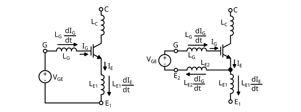
The IGBT chip connects to the package via bond wires, which, like any conductor, have both resistance and inductance. The package leads also introduce additional resistance and inductance into the circuit. During switching, rapid changes in current generate a voltage across the inductance (Ve = L*di/dt), which affects the gate-emitter voltage (Vge). When turning on, Vge = Vg – Ve, which slows down the turn-on process and increases switching losses. Similarly, during turn-off, Vge = Vg + Ve, which slows down the turn-off process and increases losses further.
The 4-pin TO-247-4L package adds an extra bond wire and lead for the emitter. The IGBT driver connects between the gate (G) and this lead. Since the driver current is much smaller than the current switched by the IGBT, the additional wire inductance has a much smaller effect on Vge.
Diotec IGBT
Diotec’s current IGBT range features a trench gate field-stop structure and includes antiparallel diodes.
These IGBTs are available in three speed categories, marked by the letters S, M, and F:
- S – up to 20 kHz (reSonant switching)
- M – up to 50 kHz (Medium-speed switching)
- F – up to 100 kHz (Fast switching).
Diotec currently has 7 IGBT models in its lineup, with plans to release 17 new IGBTs soon and add IGBTs in SMD packages in the near future.
Applications
- Induction heating – for cooktops and industrial applications (S)
- Motor drive inverters – for EVs and appliances (F)
- Solar power inverters (M)
- Uninterruptible power supply (UPS) (M)
- Heating using positive temperature coefficient (PTC) heaters (M)
- Power factor correction (PFC) (F)
- Welding machines. (F, M)
Explore our wide range of Diotec diodes and transistors, all in stock and ready for your projects. If you're looking for something specific, we can easily source additional models directly from the manufacturer with great terms.
Your feedback helps us create truly useful content for our readers. Appreciate the above information with an imaginary contribution for this article.
If you have any questions or comments, please don't hesitate to contact us. Thanks again for your time and trust.
Need more information or technical advice on selecting the right Diotec product? Have a question or request? Feel free to get in touch – we’re here to help.
Do you like our articles? Do not miss any of them! You do not have to worry about anything, we will arrange delivery to you.


