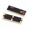
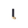
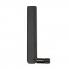
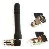
Selecting an antenna can be quite a demanding task. Our goal is to facilitate the research, development, and validation of your manufacturing process. In order to do that, we can use the technical knowledge of our engineers and 2J Antennas project management with the possibility of testing and certification. An experienced engineering team can provide comprehensive product development assistance to adapt the correct antenna to the customer's design criteria.
Internal antennas are divided into the following groups:
- Adhesive Flexi / Rigid antennas ( 4G LTE, WiFi 2.4/5.0 GHz , GNSS, ISM 868/915 MHz )
- Surface mount antennas (SMD) (4G LTE - WiFi 2.4/5.0 GHz - GNSS - ISM 868/915 MHz )
- THT antenna mount ( GNSS - IRIDIUM (Satellite) - ISM 868/915 MHz - WiFi 2.4/5.0 GHz )
Guideline for Internal Antenna integration:
Adhesive Flexi/Rigid Antennas
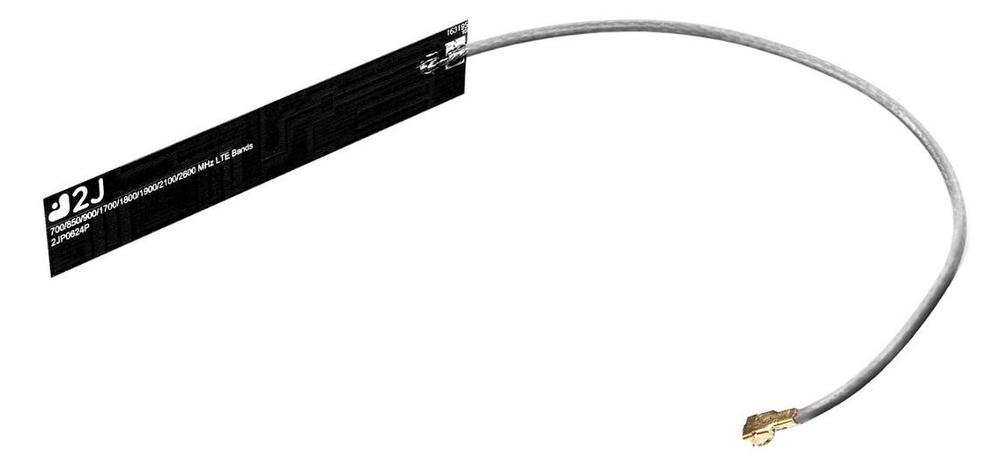
We recommend keeping the original antenna cable length or increasing the cable length for better return loss and efficiency. If the original cable length is too long, try routing the cable inside of the device with a simple U-turn to avoid reducing the original length. If reducing cable length is the only option, we have a team of highly qualified engineers available to recommend the best alternative solutions and maximize antenna performance within the modification requirements.
For optimal antenna performance, the following variables should be considered during the integration process:
- Position
- Orientation
- Cable Routing
- Cable Length
- Tuning matching components
LTE
GNSS ISM WIFI
- Find the correct position and orientation of the antenna.
- Keeping the original cable length or shorten via U-Turn method will improve the tuning and matching (Pic.1)
(Pic. 1)
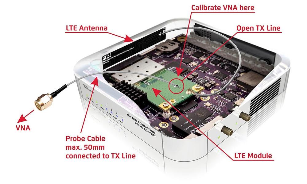
- Performing measurements with antenna cable connected to the device connector, installing a probe cable along the TX line towards the module and opening the connection of the module.
- We can check tuning and matching after antenna is integrated to determine if additional matching/tuning components are necessary.
- Housing cannot be made of ferrous materials, because metal causes interference and reduction of signal quality.
(Pic.2)
LTE ISM
- LTE or cellular antennas must be installed perpendicular to the PCB. Avoid antenna parallel installations as this reduces the radiation efficiency and/or picks up all the noise from the surrounding components. (Pic.2)
- A minimum distance of 15 mm from any metal components is required.
WIFI GNSS or HIGH FREQUENCY
- Cable length can be adjusted but we recommend preserving the original length and finding a way to route cable inside device housing.
- The antenna can be installed parallel or perpendicular.
- A minimum distance of 8 mm from any metal components is required.
for SMT antennas
ISM LTE GNSS WIFI
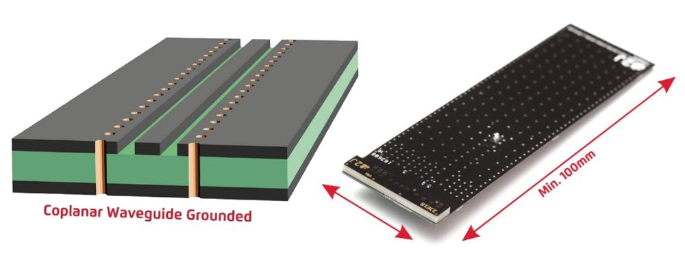
- We recommend using a short CPW-G (coplanar waveguide grounded) in TX-line design. (Pic.3)
- For optimal antenna performance, follow the instructions specified in our datasheets (dimensions, mounting pads, patterns, matching/tuning components, location, etc.)
- The length of the ground plane extending to the antenna is very important for optimal matching and efficiency.
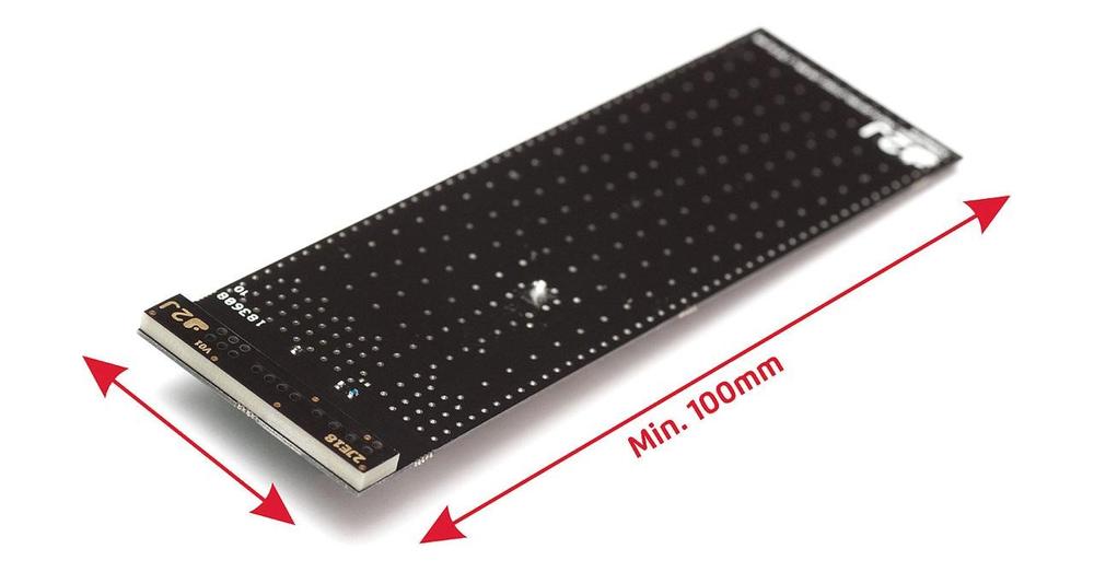
- A slimmer ground-plane width area is a better condition for installation requirements within the device. For LTE applications, we recommend 100mm minimum length of ground plane (example 2JE18). (Pic.4)
LTE ISM
- To improve radiation efficiency, position antenna on the shortest side of the board. (Pic.4)
WIFI GNSS
- You can place the antenna on any side.
GNSS ISM WIFI
- TShape of ground plane can vary.
ISM
- Minimal length of 60 mm of ground plane area for ISM.
GNSS
- Minimum length of 50 mm of ground plane area for GNSS.
WIFI
- Minimum surface area of 30 mm for ground plane for WIFI.
Recommendation for installation/placement on board:
Position / Minimum surface area in mm | |
LTE/ ISM | Placing the antenna on the shortest side of the board to improve the radiation efficiency (See Pic. 4) |
WiFi/ GNSS | Placing the antenna on any side of the board. |
GNSS/ ISM/ WiFi | Ground plane restrictions can vary. |
ISM | Minimum 60 mm for ground plane surface area. |
GNSS | Minimum 50 mm for ground plane surface area. |
WiFi | Minimum 30 mm for ground plane surface area. |
Thru-Hole Mount Antennas
- Thru-hole mount patch (THT) antennas are ideal for devices that require durability in extreme conditions. These antennas are best installed on metal surfaces that serve as a grounding point and offer flexibility on antenna orientation and position. As with all antennas, we always recommend confirming the impedance and tuning after every installation.
- 2J Antennas offers off-the-shelf development kits for the most of our THT antennas to minimize the need for customizations.
- Minimum ground plane of 40x40mm is recommended for GNSS, satellite or WIFI. For ISM standard, we recommend a minimum 50x50 mm ground plane surface area.
We are fully aware of the fact that antenna selection requires special skills. If you are in doubt, consult our experts. Our engineers will help you choose the proper antenna and ensure the success of you product on the market.
SOS electronic is a strong partner with experience. We can stand by you from the beginning of the project development to its finalization and our above-standard relations with the partner 2J Antennas will guarantee you a source of quick and professional information. The success of your project is our goal. Contact us directly.
Do you like our articles? Do not miss any of them! You do not have to worry about anything, we will arrange delivery to you.

